Machine Spindle
Machine Spindle Facts
Construction of MILWAUKEE Precision Machine Spindle Products
MILWAUKEE precision machine spindle products are precision-designed and manufactured to offer close runout tolerances and high rigidity to maximize the performance of any cutting tool.
Our machine spindle options feature:
- ABEC 7 precision angular contact ball bearings
- Heavy-duty locknuts
- Heat-treated alloy shafts, precision ground with ground threads
- Housings made from stress relieved cast iron, precision ground inside and out
- Each spindle is custom-fit at assembly to offer the greatest precision in construction, and is run-in prior to shipment
Our motorized spindles feature:
- Stress relieved, ground, fabricated steel belt housings with belt tension adjustment
- Choice of gearbelt or V belt drives. Herringbone belt drive optional
- American-made induction motors
Cartridge vs. Block Spindle
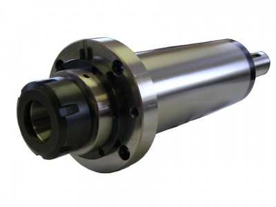
A cartridge spindle has a cylindrical body suitable for mounting in a precision bore. The mounting bore may be in a mounting bracket or a saddle of a machine slide. The cartridge spindle design offers the ability to change out a spindle without having to tram in the replacement spindle. In this way, a spare spindle can be stocked, and production down time can be minimized should replacement be required.
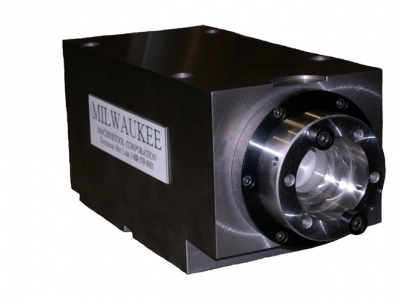
A block spindle has a rectangular body suited for mounting on a flat surface. The bearings sit directly in the mounting block, offering a higher rigidity than the cartridge design. Replacement entails removal of the entire spindle block from the machine, and requires a tram upon installation.
Seal Configurations
MILWAUKEE machine spindle products utilize either a contact seal or a non-contact labyrinth seal.
Contact seals
- Generate frictional heat and limit spindle speeds
Do not require air purge and provide the best seal
Labyrinth seals
- Suited for higher spindle speeds
- Require air purge
- A contact seal is the first choice unless higher speeds are required
Belt Drives
An offset belt drive is used to achieve machine spindle speeds higher or lower than the drive motor speed with the corresponding change in torque. It is also required when mechanisms must extend off the drive end of the spindle shaft (i.e. power drawbar, rotary coolant union).
Vee belt drives
A vee belt drive is a non-synchronous drive that offers a very smooth rotating action, and is suited for applications such as grinding or finish boring. Spindle orientation requires direct encoder.
Gear belt drives
Being a synchronous drive, there is no slippage of the drive, and positive torque transmission is assured. Spindle orientation is possible
Herringbone belt drives
Is a type of gear belt drive with a chevron-shaped tooth pattern for very smooth rotating action and quiet operation. The tooth profile is of an involute form for consistent speed regulation.
Spindle Drive Motors
A motorized spindle can be driven with an electric, air or hydraulic motor. The motor can be directly coupled to the spindle shaft, or offset with a belt drive.
Induction Motor
An induction motor is a AC, 60Hz motor that generally has fixed base speeds of 3500, 1750 or 1160 RPM. If constructed with appropriate insulation, the motor may be used with a variable frequency drive (PWM) to achieve variable speed control. An encoder may be added for closed-loop speed control.
Spindle Motor
Is an AC variable frequency motor with encoder that offers a large speed range and excellent speed regulation. Typically has features such as spindle orient and N=, N< and N> functions. For use with a matched electric spindle drive.
Air or Hydraulic Motors
Are generally used when electric power is not available, or high torque at low speed is required (hydraulic motor)
Gearmotor Drives
In certain cases when slower spindle speeds are required, a gearmotor drive is required. This occurs usually for speeds below 500 RPM. The gearmotor can be directly coupled the spindle shaft, or offset with a belt drive.
Drawbars
For NMTB, CAT, BT or HSK tooling, a drawbar must be used to retain the tool in the spindle. The drawbar may be either power or manually actuated
Manual Drawbar
- Design is that of a simple draw bolt; drawbar threads into back of toolholder
- Least expensive
Required access to the back of the spindle; hand tools are required to change cutting tool - Coolant / air thru capable if equipped with appropriate rotary union
- Best suited for occasional tool changes
- For NMTB, CAT and BT nose tapers
Power Drawbar – Rotating Drawbar Type
- Uses the draw bolt concept, but driven with a air motor
- No hand tools required to change cutting tool
- Suited for occasional tool changes only
- Shop air required
- Coolant thru not possible
- For NMTB, CAT and BT nose tapers
Power Drawbar – Spring Loaded Gripper Type
- Spring-loaded grippers clamp onto pull stud on back of toolholder
- Fastest clamp / unclamp times
- Coolant / air thru capable if equipped with appropriate rotary union
- Hydraulic power required to actuate drawbar
- Suited for production use with automatic tool changer
- For CAT, BT and HSK nose tapers
Bearings and Arrangements
ABEC 7 angular contact bearings in the nose and drive ends of the spindle feature both radial and axial load capacities. The nose bearings of MILWAUKEE spindles are generally installed with a solid preload, meaning axial and radial play are zero.
All-Steel
This is the standard bearing used in all MILWAUKEE spindles.
Hybrid Ceramic
A hybrid ceramic bearing uses ceramic balls with steel inner and outer races. The primary advantages of a hybrid bearing is increased speed capability and rigidity. Hybrid ceramic bearings typically have max speeds 15-20% greater than an all-steel bearing. This may eliminate the requirement for a separate air / oil system for the spindle. Hybrids also permit longer grease life, due to lower heat generation. Hybrid bearings are 2 –3 times the cost of standard bearings.
Duplex and Triplex Nose Sets
MILWAUKEE spindles are available with either a pair (duplex) or a trio (triplex) of bearings at the nose end of the spindle. The duplex arrangement is suited for primarily radial loading. The triplex arrangement has more radial and axial capacity than the duplex set and is suited for axially loaded applications such as drilling.
For heavily loaded applications, a quad set of nose bearings is also available. Contact MILWAUKEE for details.
Lubrication
Machine tool spindles are lubricated with either grease or oil. The choice of of lube type determines the speed capability, and in some cases, the life of the spindle.
Grease Lubrication
Each bearing is charged with a measured amount of high performance synthetic grease. Life of the grease is finite and heavily dependant on operating temperature. The life of the bearing may be limited by the grease life instead of the fatigue life of the bearings. No maintenance is required, and relube provisions are not included.
All greased bearings are charged in a clean room environment to extend lubricant life.
Air / Oil Lubrication
Each bearing is supplied with one or more nozzles that inject a small amount of oil onto the bearing. Viscous drag and heat are notable reduced, permitting higher speeds. Because the bearing always has a supply of fresh lubricant, life can be infinite if designed appropriately. The system requires a separate metering unit, and must be supplied with compressed air and oil during operation.
Spindle Nose Adaption
The spindle nose adaption is the configuration of the front end of the spindle that interfaces with either the cutting tool holder or other driven component
Steep Taper – NMTB, CAT, BT
These spindle tapers are commonly used in the metal cutting industry to allow easy changing of the cutting tool.
NMTB – Available in 30, 40 and 50 sizes, is for use with either a manual or rotary power drawbar.
CAT, BT – For use with manual or power drawbars, these designs are usually for use with automatic tool changers
HSK
A design that features simultaneous face / taper contact and is suited for high speed operation. Must have gripper type power drawbar (design is different than the steep taper power drawbars)
Boring Nose
This design uses a precision pilot bore with a flat face and bolt pattern. The tooling is usually custom-made for the application.
Arbor Nose
The arbor nose is a design that features a shaft with pilot for mounting cutting tool.
Other adaptions, such as collet, lathe nose and Morse taper are also available.
Cutting Tool Coolant
Cutting tool coolant is used for machining operations where excess heat must be removed or chips must be evacuated.
Coolant Thru
The term coolant thru means that coolant is delivered through the cutting tool directly at the cutting edge. Can be supplied to the cutting tool via a hollow drawbar and rotary union.
Flood Coolant
Flood coolant consists of nozzles mounted at the front of the spindle to direct coolant externally to the cutting tool.
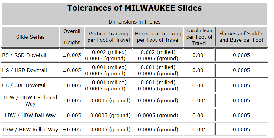
Runouts