
Multi-Axis Modules
Slide Modules
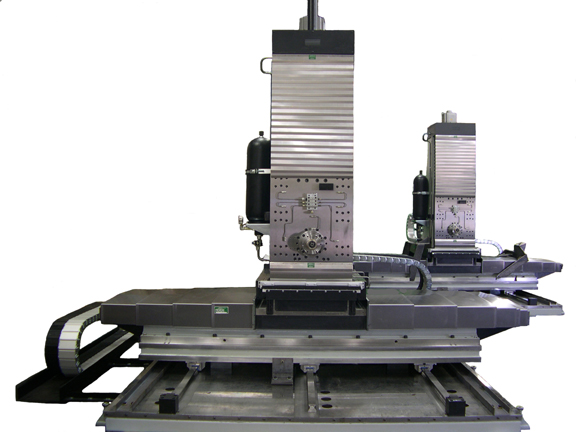
Four axis (compounded X-Z-Y with fourth axis moving base three rail slide arrangement)
Special multi-axis module slide and spindle arrangement for Boeing A-10 Re-wing project. Features include rotating nut with precision ballscrew for vertical travel. Closed loop counter-balance system with 5-gallon accumulator. (Cylinders not shown). All axises include precision class heavy pre-load recirculating roller way elements. Fourth axis includes pneumatic and manual clamping features for vibration, positive locking, and positional repeatability for the three-axis unit. (Walk-on-way covers with hinged plates not shown).
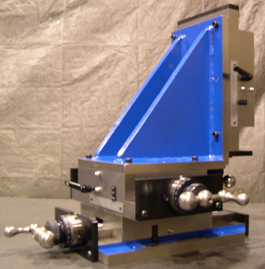
Three axis (X-Y-Z slide with angle plate arrangement)
For a three-axis motion system, two slides are mounted directly together, and then a third is mounted vertically atop the two using an angle plate. This provides three axes of linear motion.
Slide / Spindle Modules
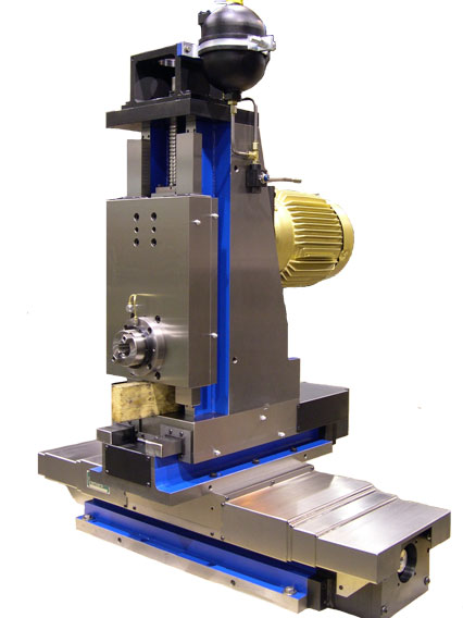
Single axis vertical slide and spindle units
This type of module features a motorized spindle, vertical slide and precision angle plate or column to provide a single axis of linear motion. The module can be of three configurations:
- Horizontal cartridge spindle mounted in the saddle of a vertical slide
- Horizontal block spindle mounted atop a precision angle plate, both mounted to the saddle of a vertical slide
- Vertical block / cartridge spindle mounted directly to the saddle of a vertical slide

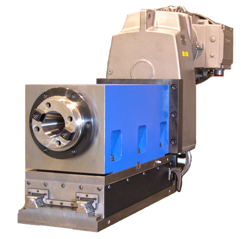
Single axis horizontal slide and spindle units
Typically used for drilling and boring operations, a motorized spindle is mounted atop a horizontal slide.
Three axis modules with spindles
A three axis module consists of two compounded slides with a precision column and motorized spindle. The spindle may be horizontal or vertical, and may be of a block or cartridge design.
Design of Multi-Axis Modules
Pyramid Profile
Slide overhang – When slides are compounded, one of the two units will not be supported for its entire length. This cantilevered section must be considered when sizing the slides.
Slide size order – For maximal stability, wider slides are used on the bottom of a multi-axis assembly than are used on the top. This minimizes deflection and increases accuracy.
Counterbalance for Vertical Axis
Definition – A counterbalance is a mechanism that continuously supports the weight of a saddle and spindle.
Rationale – The vertical axis slide supports the weight of its own saddle, and that of the motorized spindle. For vertical axes driven with an electric motor, the motor must constantly energize a field to support the static weight. The motor and drive must be oversized to handle the thermal load of this condition. In a loss of power situation, the vertical axis may fall if a brake is not used on the motor. Each of these situations can be changed with the addition of a counterbalance.
Design – The counterbalance may be of four types: weight stack, pneumatic cylinder, hydraulic cylinder, or air over hydraulic cylinder.
- A weight stack counterbalance connects a stack of steel plates to the reciprocating weight via chains or cables, and pulls the saddle upward.
- Pneumatic cylinder counterbalance connects one or two air cylinders to the reciprocating weight, and requires a constant supply or air pressure to operate.
- The hydraulic counterbalance substitutes hydraulic cylinders for the pneumatic cylinders. Constant hydraulic pressure is required to operate.
- An air over hydraulic counterbalance uses a hydraulic cylinder supplied with pressure from a charged accumulator. This system is self-contained and does not rely on external air or hydraulic pressure. Because the lifting power comes from an accumulator, the amount of counterbalance is not constant.