Machine Spindle Selection Guide for Metal Cutting
Not sure what type of spindle fits your application? Our team can help evaluate your cutting requirements and identify an appropriate spindle size and configuration.
Factors to Consider When Choosing a Machine Spindle
Understanding how to choose a machine spindle starts with the workpiece, tooling, cutting forces and machine configuration.
Workpiece Material
- Material Type: Different metals create different cutting forces, which can affect spindle size and performance requirements.
- Hardness: Harder materials may place greater demands on spindle rigidity and power.
- Surface Condition: Workpiece condition can influence cutting behavior, tool loading and spindle requirements.
- Depth of Cut: Review both axial and radial cutting depths when comparing spindles for metal cutting.
Gage Length
- Tool Extension: Longer gage lengths increase tool-end deflection and can reduce rigidity.
- Deflection: Doubling tool gage length can increase deflection by a factor of eight.
- Spindle Size: A larger spindle and tool holder may help compensate for longer tooling. Moving from a 40-taper to a 50-taper spindle is one possible approach.
- Speed Capacity: When considering a larger spindle, confirm its operating speed still matches the application.
Spindle Orientation
- Mounting Position: Determine whether the spindle will operate horizontally, vertically or in another orientation.
- Machine Layout: Orientation can affect how the spindle fits within the overall equipment design.
- Loading Conditions: Review spindle position alongside the direction of cutting forces and machining requirements.
- Installation Space: Confirm sufficient clearance for the selected spindle orientation and surrounding components.
Power Output
- Horsepower: Choose a spindle capable of transmitting the power required for the machining operation.
- Thrust: Account for expected cutting loads when reviewing spindle capacity.
- Speed: Match spindle speed capability with tooling and production requirements.
- Application Demands: Heavier cuts may prioritize power capacity, while other operations may place greater emphasis on spindle speed.
Boring Application
- Bore Diameter: Select a spindle with a nose bearing inside diameter larger than the bore being machined.
- Duplex Bearing Set: Suited primarily for radial loading.
- Triplex Bearing Set: Suited for combined radial and axial loading.
- Quadruplex Bearing Set: Used where extra-high bearing capacity is required.
- Bearing Arrangement: Match spindle nose bearing selection with the anticipated cutting loads.
Space Limitations
- Installation Envelope: Review available machine space before selecting spindle size.
- Spindle Dimensions: Account for the spindle body, nose and surrounding machine components.
- Orientation: Mounting position can affect the amount of space required.
- Larger Spindle Options: When two sizes meet the application requirements, a larger spindle may provide greater rigidity or capacity if sufficient space and speed capability are available.
Milwaukee MachineTool Spindle Types
Block Spindles
Block spindles use an integrated block-style housing designed for direct incorporation into machine assemblies. This configuration can provide a practical mounting solution for machine builders seeking a rigid spindle package for metal cutting applications.
- Integrated block-style spindle housing
- Multiple spindle sizes available
- Suitable for production machining and custom machine designs
- Available in several Milwaukee MachineTool MB Series configurations
- Designed for integration with compatible machine structures and drive systems
Cartridge Spindles
Cartridge spindles use a cylindrical package intended for installation within a supporting machine housing or structure. Their form can be useful when the spindle must fit into an existing assembly or when machine design calls for a compact spindle package.
- Cylindrical cartridge-style construction
- Designed for installation within a supporting housing
- Multiple spindle sizes and configurations available
- Available across several Milwaukee MachineTool MC Series models
- Suitable for a range of metal cutting and machine-building applications
Motorized Spindles
Motorized spindles combine spindle rotation and motor power within an integrated assembly. They can be a strong option when machine design, spindle speed and power requirements favor a self-contained drive arrangement.
- Integrated spindle and motor configuration
- Available for applications with defined speed and power requirements
- Helps reduce the need for a separate external spindle drive arrangement
- Performance options can be compared using Milwaukee MachineTool motorized spindle data
- Suitable for custom machining systems with specific packaging requirements
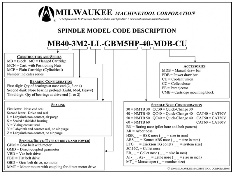
Spindle Model Code Description