
Linear Guide Machine Slides
Milwaukee MachineTool manufactures low- and high-profile linear guide slides for machine tool, production and automation applications that require smooth travel, controlled positioning and dependable load support. These precision slides use linear bearing rails to guide accurate motion across a range of machine layouts and space constraints.
Ball-bearing and roller-bearing configurations, along with available drive-screw options, give engineers flexibility when balancing friction, rigidity, load capacity, travel and available space. Our engineers can help compare slide profile, bearing style, travel, mounting and drive requirements—or determine whether a modified or custom solution is appropriate. Talk with an MMT engineer or send us your drawings.
Low-Profile Linear Guide Slides (LRW / LBW) Series
The LRW and LBW Series share a compact, low-profile design for machine layouts where available space, controlled travel and reliable linear guidance are important. LRW slides use preloaded roller bearings for greater rigidity, load support and vibration damping. LBW slides use preloaded ball bearings for lower friction and higher traverse speed.
Low-Profile Linear Guide (LRW/LBW) Series Features
- Compact low-profile construction
- LRW: preloaded linear roller bearings for higher rigidity and load support
- LBW: preloaded linear ball bearings for lower friction and higher traverse speed
- Precision-ground surfaces and aligned linear rails
- Sealed bearing blocks with lubrication provisions
- Each slide tested before shipment
Low-Profile Linear Guide (LRW/LBW) Series Specs
Review dimensions, travel ranges, mounting details, bearing configuration, drive-screw options and weight to select the right low-profile slide for your application.
Choose the LRW roller-bearing configuration when rigidity, load support and vibration damping are the primary concerns. Choose the LBW ball-bearing configuration when lower friction and higher traverse speed are more important.
Low Profile Linear Guide Slide Size Guide
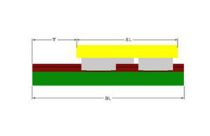
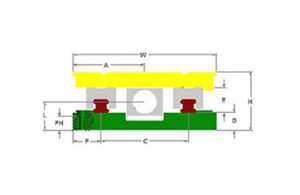
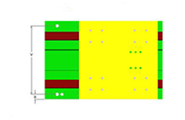
Low Profile Linear Guide Slide Dimensions (LBW / LRW) |
||||||||||||||
|---|---|---|---|---|---|---|---|---|---|---|---|---|---|---|
| Dimensions in Inches | ||||||||||||||
| Model | Width W | H | C | E | FH | Y | F | D | A | B | L | CL | T-BL | Mtg Screw |
| LBW6 LRW6 | 6.00 | 3.00 | 3.14 | .94 | .75 | 4.90 | 1.43 | 1.03 | 3.00 | .55 | 1.38 | ≥6 | To Your Specs BL=CL+T +2 | 3/8 |
| LBW8 LRW8 | 8.00 | 3.25 | 4.26 | 1.18 | .75 | 6.56 | 1.87 | 1.03 | 4.00 | .72 | 1.62 | ≥8 | 3/8 | |
| LBW10 LRW10 | 10.00 | 3.75 | 5.74 | 1.42 | .81 | 8.36 | 2.13 | 1.17 | 5.00 | .82 | 1.88 | ≥10 | 1/2 | |
| LBW12 LRW12 | 12.00 | 4.00 | 6.54 | 1.89 | .75 | 9.96 | 2.73 | 1.06 | 6.00 | 1.02 | 2.00 | ≥12 | 1/2 | |
| LBW16 LRW16 | 16.00 | 5.00 | 8.58 | 2.36 | .94 | 13.22 | 3.71 | 1.32 | 8.00 | 1.39 | 2.50 | ≥16 | 5/8 | |
| LBW20 LRW20 | 20.00 | 6.00 | 10.90 | 2.76 | 1.31 | 16.42 | 4.55 | 1.62 | 10.00 | 1.74 | 3.00 | ≥20 | 5/8 | |
| LBW24 LRW24 | 24.00 | 7.00 | 12.48 | 3.35 | 1.56 | 19.50 | 5.76 | 1.83 | 12.00 | 2.25 | 3.50 | ≥24 | 5/8 | |
Low Profile Linear Guide Slide Drive Screw Configurations Chart
Low Profile Linear Guide Slide Drive Screw Configurations (LBW / LRW) |
||||
|---|---|---|---|---|
| Dimensions in inches | ||||
| Slide Width | Lead Screw Drive | Ballscrew Drive | ||
| Vee Thread RH | ACME Thread RH | Rolled RH | Ground RH |
|
| 6 | 5/8-20 TPI | 5/8-10 TPI | Ø0.625 x 0.200 lead | Ø0.625 x 0.200 lead |
| 8 | 3/4-20 TPI | 3/4-10 TPI | Ø0.750 x 0.200 lead | Ø0.750 x 0.200 lead, x 0.250 lead |
| 10 | - | 1-10 TPI | Ø1.000 x 0.200 lead | Ø1.000 x 0.200 lead, x 0.250 lead |
| 12 | - | 1-10 TPI | Ø1.250 x 0.200 lead | Ø1.250 x 0.200 lead, x 0.250 lead |
| 16 | - | 1 1/4-10 TPI | Ø1.250 x 0.200 lead | Ø1.250 x 0.200 lead, x 0.250 lead |
| 20 | - | 1 1/4-10 TPI | Ø1.500 x 0.200 lead | Ø1.500 x 0.200 lead, x 0.250 lead |
| 24 | - | 1 1/2-10 TPI | Ø2.000 x 0.200 lead | Ø2.000 x 0.200 lead, x 0.250 lead |
| TPI = Threads Per Inch - Metric leads are available | ||||
| • Leadscrew drives come with preloaded needle thrust bearings, micrometer dial and hand crank | ||||
| • Ballscrew drives come with preloaded ball bearing drive support unit | ||||
Linear Guide Specifications*
Linear Guide Specifications* |
|||||
|---|---|---|---|---|---|
| Slide Width (inch) | Bearing Size (mm) | Basic Load Capacity Ball Bearing (lb) | Basic Load Capacity Roller Bearing (lb) |
||
| Static | Dynamic | Static | Dynamic | ||
| 6, 7, 8 | 15 | 3035 | 1750 | 4470 | 2115 |
| 9, 10 | 25 | 6835 | 5125 | 15,735 | 7485 |
| 12, 15 | 35 | 12,140 | 9420 | 33,565 | 15,670 |
| 16, 18, 20, 24 | 45 | 19,265 | 15,310 | 57,685 | 26,795 |
| 32 | 55 | 27,290 | 20,020 | 77,630 | 37,095 |
| * For comparative purposes only - Contact Us for slide selection | |||||
Linear Guide Slide Cylinder Drive Specifications |
||||
|---|---|---|---|---|
| Dimensions in inches | ||||
| Slide Width | Heavy Duty Pneumatic Cylinder | Medium Duty Hydraulic Cylinder* | ||
| Bore Ø (in) | Max Pressure (PSI) | Bore Ø (in) | Max Pressure (PSI) | |
| 6, 7 | 2.5 | 250 | 2.0 | 500 |
| 8, 9 | 3.25 | 250 | 2.5 | 300 |
| 10, 12 | 4.0 | 250 | 3.25 | 650 |
| 15 | 5.0 | 250 | 4.0 | 450 |
| 16, 18 | 6.0 | 250 | 4.0 | 450 |
| 20 | 6.0 | 250 | 4.0 | 450 |
| 24 | 6.0 | 250 | 5.0 | 300 |
| * With head rectangular flange mounting; other styles have higher pressure ratings | ||||
| • Cylinders come equipped with adjustable cushions on both ends | ||||
| • Linear alignment rod coupling and adjustable stop rod are standard on all cylinder powered slides | ||||
High-Profile Linear Guide Slides (HRW / HBW) Series
The HRW and HBW Series combine high-profile slide construction with preloaded linear bearings for applications requiring rigid, accurately guided motion. HRW slides use roller bearings for greater rigidity, load support and vibration damping. HBW slides use ball bearings for lower friction and higher traverse speed.
These slides are suited to machine tools, production equipment and automation systems where slide height, load, travel and bearing selection must be considered together.
High Profile Linear Guide (HRW/HBW) Series Features
- High-profile construction for demanding machine layouts
- HRW: preloaded linear roller bearings for rigidity, load support and vibration damping
- HBW: preloaded linear ball bearings for lower friction and higher traverse speed
- Precision-ground surfaces and aligned linear rails
- Sealed bearing blocks with lubrication provisions
- Each slide tested before shipment
High Profile Linear Guide (HRW/HBW) Series Specs
Review dimensions, travel ranges, mounting details, bearing configuration, drive-screw options and weight to match the high-profile slide to your load, stroke and available machine space.
Choose the HRW roller-bearing configuration for higher rigidity and heavier or more demanding machining conditions. Choose the HBW ball-bearing configuration when lower friction and faster travel are the priority.
High Profile Linear Guide Slide Size Guide
Please refer to the figures below in correlation with the dimensions chart.
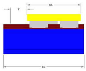
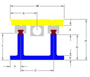
High Profile Linear Guide Slide Dimensions (HBW / HRW) |
||||||||||||
|---|---|---|---|---|---|---|---|---|---|---|---|---|
| Dimensions in Inches | ||||||||||||
| Model | Width W | H | C | E | F | D | A | B | L | CL | T-BL | Mtg Screw |
| HBW7 HRW7 | 7.00 | 5.00 | 3.57 | .94 | 1.72 | 3.06 | 3.50 | .65 | 2.75 | ≥7 | To Your Specs BL=CL+T +2 | 3/8 |
| HBW9 HRW9 | 9.00 | 6.38 | 3.50 | .75 | 1.50 | 2.13 | 1.13 | 1.00 | 3.88 | ≥9 | 1/2 | |
| HBW12 HRW12 | 12.00 | 7.50 | 5.00 | 1.25 | 2.25 | 3.02 | 1.30 | 1.30 | 5.53 | ≥12 | 5/8 | |
| HBW15 HRW15 | 15.00 | 9.50 | 5.50 | 1.50 | 2.88 | 3.76 | 1.50 | 1.50 | 6.38 | ≥15 | 5/8 | |
| HBW18 HRW18 | 18.00 | 10.00 | 8.00 | 1.75 | 3.50 | 4.01 | 1.75 | 1.80 | 7.18 | ≥18 | 3/4 | |
| HBW24 HRW24 | 24.00 | 12.00 | 12.00 | 2.00 | 4.00 | 4.01 | 2.13 | 2.00 | 8.31 | ≥24 | 3/4 | |
| HBW32 HRW32 | 32.00 | 13.00 | 20.00 | 2.00 | 4.00 | 4.96 | 2.13 | 2.00 | 8.31 | ≥32 | 3/4 | |
High Profile Linear Guide Slide Drive Screw Configurations Chart
High Profile Linear Guide Slide Drive Screw Configurations (HBW / HRW) |
||||
|---|---|---|---|---|
| Dimensions in inches | ||||
| Slide Width | Lead Screw Drive | Ballscrew Drive | ||
| Vee Thread RH | ACME Thread RH | Rolled RH | Ground RH |
|
| 7 | - | Ø1.000-0.100 lead | Ø1.000-0.250 lead | Ø1.000-0.250 lead |
| 9 | - | Ø1.250-0.100 lead | Ø1.500-0.250 lead | Ø1.250-0.250 lead |
| 12 | - | Ø1.500-0.100 lead | Ø1.500-0.250 lead | Ø1.500-0.250 lead |
| 15 | - | Ø2.000-0.200 lead | Ø2.000-0.500 lead | Ø2.000-0.500 lead |
| 18 | - | Ø2.000-0.200 lead | Ø2.000-0.500 lead | Ø2.000-0.500 lead |
| 20 | - | Ø2.500-0.250 lead | Ø2.500-0.500 lead | Ø2.500-0.500 lead |
| 24 | - | Ø2.500-0.250 lead | Ø2.500-0.500 lead | Ø2.500-0.500 lead |
| TPI = Threads Per Inch - Metric leads are available | ||||
| • Leadscrew drives come with preloaded needle thrust bearings, micrometer dial and hand crank | ||||
| • Ballscrew drives come with preloaded ball bearing drive support unit | ||||
Linear Guide Specifications*
Linear Guide Specifications* |
|||||
|---|---|---|---|---|---|
| Slide Width (inch) | Bearing Size (mm) | Basic Load Capacity Ball Bearing (lb) | Basic Load Capacity Roller Bearing (lb) |
||
| Static | Dynamic | Static | Dynamic | ||
| 6, 7, 8 | 15 | 3035 | 1750 | 4470 | 2115 |
| 9, 10 | 25 | 6835 | 5125 | 15,735 | 7485 |
| 12, 15 | 35 | 12,140 | 9420 | 33,565 | 15,670 |
| 16, 18, 20, 24 | 45 | 19,265 | 15,310 | 57,685 | 26,795 |
| 32 | 55 | 27,290 | 20,020 | 77,630 | 37,095 |
| * For comparative purposes only - Contact Us for slide selection | |||||
Linear Guide Slide Cylinder Drive Specifications |
||||
|---|---|---|---|---|
| Dimensions in inches | ||||
| Slide Width | Heavy Duty Pneumatic Cylinder | Medium Duty Hydraulic Cylinder* | ||
| Bore Ø (in) | Max Pressure (PSI) | Bore Ø (in) | Max Pressure (PSI) | |
| 6, 7 | 2.5 | 250 | 2.0 | 500 |
| 8, 9 | 3.25 | 250 | 2.5 | 300 |
| 10, 12 | 4.0 | 250 | 3.25 | 650 |
| 15 | 5.0 | 250 | 4.0 | 450 |
| 16, 18 | 6.0 | 250 | 4.0 | 450 |
| 20 | 6.0 | 250 | 4.0 | 450 |
| 24 | 6.0 | 250 | 5.0 | 300 |
| * With head rectangular flange mounting; other styles have higher pressure ratings | ||||
| • Cylinders come equipped with adjustable cushions on both ends | ||||
| • Linear alignment rod coupling and adjustable stop rod are standard on all cylinder powered slides | ||||
Need Help Selecting the Right Slide?
Milwaukee Machine Tool works with OEMs, machine builders and equipment designers to select, modify or develop machine slide solutions around the application. We can help evaluate load, travel, accuracy, drive, space and environmental requirements—from standard slides to custom configurations.
Discuss your application with an MMT engineer. Send us your drawings or requirements, and we’ll help determine the right next step.