
Contoured Base Dovetail Machine Slides
Milwaukee MachineTool manufactures CB and CBF Series contoured-base dovetail machine slides for heavy-load applications requiring rigid saddle support, controlled travel and flexible drive integration. The contoured base incorporates a recessed area for a leadscrew, ballscrew or cylinder drive, allowing the drive mechanism to remain stationary while the saddle moves through its stroke. This gives engineers greater flexibility when packaging the slide into specialized machine designs.
CB and CBF Series slides are suited to OEM equipment, production machinery and custom machine applications where load, mounting style, drive configuration and available space must be considered together. Our engineers can help compare models and determine whether a standard or modified configuration best fits your requirements. Talk with an MMT engineer or send us your drawings.
Contoured Base (CB) Slide Series
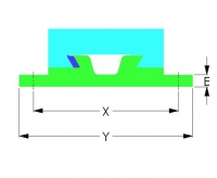
The Contoured Base (CB) Slide Series is designed for accuracy under heavy loading conditions, with a base structure built to support the saddle throughout its full stroke. CB slides are a strong choice for machine tool, production and automation applications where rigidity and repeatable motion are primary concerns. You may select the Countoured Base Slide with Flanges (CBF) which provides the same heavy-duty contoured base machine slide design with flanged mounting for applications where underside or center mounting is not practical.
Contoured Base (CB) Slide Features
CB slides use a heavy-duty stress-relieved cast iron base and saddle for maximum stability. The base casting includes a recess for leadscrew, ballscrew or cylinder drive mounting, with precision ground ways, exterior surfaces, straight gib, standard lubrication provisions and factory adjustment before shipment.
Contoured Base (CB) Slide Specs
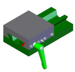
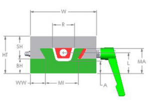
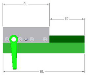
Compare CB model dimensions, slide width, mounting screw size, weight per inch of length and related measurements to match the slide body to the available machine envelope and required travel range.
Heavy Duty Contoured Base Dovetail Slide Size Guide
Please refer to the figures below in correlation with the dimensions chart.
Heavy Duty Contoured Base Dovetail Slide Dimensions |
||||||||||||||
|---|---|---|---|---|---|---|---|---|---|---|---|---|---|---|
| Dimensions in Inches | ||||||||||||||
| Model | Width W | HT | R | A | BH | Y | X | MA | WW | MI | Mtg Screw | L | Lb / inch of Length | |
| WC | WB(CB) | |||||||||||||
| CB3 CBF3 | 3.00 | 1.75 | 1.00 | .44 | .75 | 5.50 | 4.25 | 1.13 | .56 | 1.72 | 5/16 | .88 | 0.6 | 0.8 |
| CB4 CBF4 | 4.00 | 2.25 | 1.31 | .75 | .88 | 6.50 | 5.25 | 1.50 | .94 | 1.94 | 5/16 | 1.25 | 1.0 | 1.1 |
| CB6 CBF6 | 6.00 | 3.00 | 1.69 | .63 | 1.00 | 9.00 | 7.50 | 1.63 | 1.44 | 2.94 | 3/8 | 1.25 | 1.7 | 2.6 |
| CB8 CBF8 | 8.00 | 3.25 | 2.00 | .88 | 1.25 | 11.00 | 9.50 | 2.00 | 1.88 | 4.00 | 3/8 | 1.63 | 3.0 | 3.2 |
| CB10 CBF10 | 10.00 | 3.75 | 3.25 | .94 | 1.31 | 13.00 | 11.50 | 2.13 | 1.88 | 6.06 | 1/2 | 1.63 | 3.9 | 5.1 |
| CB12 CBF12 | 12.00 | 4.00 | 3.50 | 1.19 | 1.56 | 16.00 | 14.00 | 2.38 | 2.19 | 7.38 | 1/2 | 1.88 | 5.5 | 5.7 |
| CB16 CBF16 | 16.00 | 5.00 | 4.38 | 1.38 | 1.75 | 20.00 | 18.00 | 3.13 | 3.06 | 9.50 | 5/8 | 2.38 | 8.9 | 10.0 |
| CB20 CBF20 | 20.00 | 6.00 | 5.50 | 1.75 | 2.12 | 25.00 | 22.50 | 3.75 | 4.06 | 11.56 | 5/8 | 3.00 | 13.6 | 15.0 |
| CB24 CBF24 | 24.00 | 7.00 | 6.00 | 2.00 | 2.50 | 30.00 | 27.00 | 4.50 | 5.56 | 12.38 | 5/8 | 3.75 | 18.5 | 20.8 |
Contoured Base with Flanges Slide Size Guide
Please refer to the figures below in correlation with the dimensions chart.
Heavy Duty Contoured Base Dovetail Slide Dimensions |
||||||||||||||
|---|---|---|---|---|---|---|---|---|---|---|---|---|---|---|
| Dimensions in Inches | ||||||||||||||
| Model | Width W | HT | R | A | BH | Y | X | MA | WW | MI | Mtg Screw | L | Lb / inch of Length | |
| WC | WB(CB) | |||||||||||||
| CB3 CBF3 | 3.00 | 1.75 | 1.00 | .44 | .75 | 5.50 | 4.25 | 1.13 | .56 | 1.72 | 5/16 | .88 | 0.6 | 0.8 |
| CB4 CBF4 | 4.00 | 2.25 | 1.31 | .75 | .88 | 6.50 | 5.25 | 1.50 | .94 | 1.94 | 5/16 | 1.25 | 1.0 | 1.1 |
| CB6 CBF6 | 6.00 | 3.00 | 1.69 | .63 | 1.00 | 9.00 | 7.50 | 1.63 | 1.44 | 2.94 | 3/8 | 1.25 | 1.7 | 2.6 |
| CB8 CBF8 | 8.00 | 3.25 | 2.00 | .88 | 1.25 | 11.00 | 9.50 | 2.00 | 1.88 | 4.00 | 3/8 | 1.63 | 3.0 | 3.2 |
| CB10 CBF10 | 10.00 | 3.75 | 3.25 | .94 | 1.31 | 13.00 | 11.50 | 2.13 | 1.88 | 6.06 | 1/2 | 1.63 | 3.9 | 5.1 |
| CB12 CBF12 | 12.00 | 4.00 | 3.50 | 1.19 | 1.56 | 16.00 | 14.00 | 2.38 | 2.19 | 7.38 | 1/2 | 1.88 | 5.5 | 5.7 |
| CB16 CBF16 | 16.00 | 5.00 | 4.38 | 1.38 | 1.75 | 20.00 | 18.00 | 3.13 | 3.06 | 9.50 | 5/8 | 2.38 | 8.9 | 10.0 |
| CB20 CBF20 | 20.00 | 6.00 | 5.50 | 1.75 | 2.12 | 25.00 | 22.50 | 3.75 | 4.06 | 11.56 | 5/8 | 3.00 | 13.6 | 15.0 |
| CB24 CBF24 | 24.00 | 7.00 | 6.00 | 2.00 | 2.50 | 30.00 | 27.00 | 4.50 | 5.56 | 12.38 | 5/8 | 3.75 | 18.5 | 20.8 |
Contoured Base Dovetail Slide With Drive Screw
The contoured base dovetail slide with drive screw is configured for controlled mechanical movement using leadscrew or ballscrew drive options. This setup gives engineers a rigid slide platform with screw-driven positioning for feed, adjustment and controlled travel applications.
Contoured Base Dovetail Slide With Drive Screw Features
Drive screw configurations are available by slide width, with lead screw and ballscrew options for different motion requirements. Leadscrew drives include preloaded needle thrust bearings, a micrometer dial and a hand crank, while ballscrew drives include a preloaded ball bearing drive support.
Contoured Base Dovetail Slide With Drive Screw Specs
Compare available drive screw configurations by slide width, including Vee thread, ACME thread, rolled ballscrew and ground ballscrew options. Use the specs to match drive type, lead, thread style and slide size to the required positioning method.
CB / CBF Contoured Base Dovetail Slide Drive Screw Size Guide
CB / CBF Contoured Base Dovetail Slide Drive Screw Configurations |
||||
|---|---|---|---|---|
| Dimensions in Inches | ||||
| Slide Width | Lead Screw Drive | Ballscrew Drive | ||
| Vee Thread RH | ACME Thread RH | Rolled RH | Ground RH |
|
| 3 | 5/16-40 TPI | 3/8-10 TPI | - | - |
| 4 | 1/2-20 TPI | 1/2-10 TPI | Ø0.375 x 0.125 lead | - |
| 6 | 5/8-20 TPI | 5/8-10 TPI | Ø0.625 x 0.200 lead | Ø0.625 x 0.200 lead |
| 8 | 3/4-20 TPI | 3/4-10 TPI | Ø0.750 x 0.200 lead | Ø0.750 x 0.200 lead |
| 10 | - | 1-10 TPI | Ø1.000 x 0.200 lead | Ø1.000 x 0.200 lead, x .250 lead |
| 12 | - | 1-10 TPI | Ø1.250 x 0.200 lead | Ø1.250 x 0.200 lead, x .250 lead |
| 16 | - | 1 1/4-10 TPI | Ø1.250 x 0.200 lead | Ø1.250 x 0.200 lead, x .250 lead |
| 20 | - | 1 1/4-10 TPI | Ø1.500 x 0.200 lead | Ø1.500 x 0.200 lead, x .250 lead |
| 24 | - | 1 1/2-10 TPI | Ø2.000 x 0.200 lead | Ø2.000 x 0.200 lead, x .250 lead |
| TPI = Threads Per Inch - Metric leads are available | ||||
| • Leadscrew drives come with preloaded needle thrust bearings, micrometer dial and hand crank | ||||
| • Ballscrew drives come with preloaded ball bearing drive support unit | ||||
Contoured Base Dovetail Slide with Cylinder Drive
The contoured base dovetail slide with cylinder drive supports powered linear movement using pneumatic or hydraulic cylinder configurations. This option works well for repetitive feed movements, automated machine cycles and applications where cylinder-driven actuation fits the operating sequence.
Contoured Base Dovetail Slide with Cylinder Drive Features
Cylinder drive configurations are available for heavy-duty pneumatic and medium-duty hydraulic applications. Cylinder drive options allow the slide to handle powered motion while maintaining the saddle support and rigidity advantages of the contoured base design.
Contoured Base Dovetail Slide with Cylinder Drive Specs
Review cylinder drive specifications by slide width, including bore size and maximum pressure ratings, to determine whether a pneumatic or hydraulic cylinder configuration fits the available space, force requirements and production cycle.
CB / CBF Contoured Base Dovetail Slide Cylinder Drive Specifications Chart
CB / CBF Contoured Base Dovetail Slide Cylinder Drive Specifications |
||||
|---|---|---|---|---|
| Dimensions in Inches | ||||
| Slide Width | Heavy Duty Pneumatic Cylinder | Medium Duty Hydraulic Cylinder* | ||
| Bore Ø (in) | Max Pressure (PSI) | Bore Ø (in) | Max Pressure (PSI) | |
| 4 | 2.0 | 250 | 1.5 | 650 |
| 6 | 2.5 | 250 | 1.5 | 650 |
| 8 | 3.25 | 250 | 2.0 | 500 |
| 10 | 4.0 | 250 | 2.0 | 500 |
| 12 | 5.0 | 250 | 2.5 | 300 |
| 16 | 6.0 | 250 | 3.25 | 650 |
| 20 | 6.0 | 250 | 4.0 | 450 |
| 24 | 6.0 | 250 | 5.0 | 300 |
| * With head rectangular flange mounting; other styles have higher pressure ratings | ||||
| • Cylinders come equipped with adjustable cushions on both ends | ||||
| • Linear alignment rod coupling and adjustable stop rod are standard on all cylinder powered slides | ||||
Need Help Selecting the Right Slide?
Milwaukee Machine Tool works with OEMs, machine builders and equipment designers to select, modify or develop machine slide solutions around the application. We can help evaluate load, travel, accuracy, drive, space and environmental requirements—from standard slides to custom configurations.
Discuss your application with an MMT engineer. Send us your drawings or requirements, and we’ll help determine the right next step.