
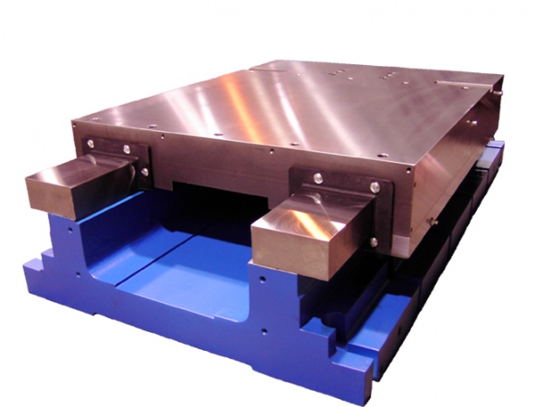
Hardened Way Slides – HHW/LHW Series
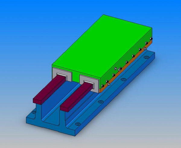
HHW
LHW
Hardened way slides are designed primarily for production machining operations where the slide must be rigid and accurate while under heavy loads and vibration. These slides offer greater stiffness and accuracy than dovetail slides, and are best suited for powered operation.
Our hardened way slides feature:
- Steel ways flame hardened to 58/60 Rc
- Low-friction bearing material which reduces friction to less than half and permits a tighter fitting slide
- Deep cavity, stress relieved cast iron bases (HHW version)
- Heavy cross-section, stress relieved cast iron saddles
- Precision surface ground mounting surfaces
- Standard way wipers
- Precision ground straight gib
- Adjustable keeper gibs
- Provisions for lubrication
- Each slide is factory-adjusted and tested prior to shipment

High Profile Hardened Way Slide Dimensions |
|||||||||||||
|---|---|---|---|---|---|---|---|---|---|---|---|---|---|
| Dimensions in Inches | |||||||||||||
| Model | Width W | H | CR | WH | WW | SH | FH | T-BL | SL | X | Y | R | Mtg Screw |
| HHW5 | 5.00 | 3.50 | 1.87 | .50 | .88 | 1.50 | .63 | To Your Specs BL=CL+T +2 | ≥5 | 1.56 | 4.25 | .375 | 5/16 |
| HHW7 | 7.00 | 5.00 | 2.13 | .75 | 1.50 | 2.13 | .75 | ≥7 | 2.44 | 6.00 | .500 | 3/8 | |
| HHW9 | 9.00 | 6.38 | 3.50 | .75 | 1.50 | 2.13 | 1.13 | ≥9 | 2.75 | 8.00 | .500 | 3/8 | |
| HHW12 | 12.00 | 7.50 | 5.00 | 1.25 | 2.25 | 3.02 | 1.30 | ≥12 | 3.50 | 10.50 | .750 | 1/2 | |
| HHW15 | 15.00 | 9.50 | 5.50 | 1.50 | 2.88 | 3.76 | 1.50 | ≥15 | 4.75 | 13.50 | .750 | 5/8 | |
| HHW18 | 18.00 | 10.00 | 8.00 | 1.75 | 3.50 | 4.01 | 1.75 | ≥18 | 5.00 | 16.00 | 1.00 | 3/4 | |
| HHW20 | 20.00 | 12.00 | 7.50 | 2.00 | 4.00 | 4.38 | 2.00 | ≥20 | 6.25 | 18.00 | 1.00 | 3/4 | |
| HHW24 | 24.00 | 12.00 | 12.00 | 2.00 | 4.00 | 4.01 | 2.13 | ≥24 | 6.00 | 22.00 | 1.00 | 3/4 | |
| HHW32 | 32.00 | 13.00 | 20.00 | 2.00 | 4.00 | 4.96 | 2.13 | ≥32 | 6.00 | 30.00 | 1.00 | 3/4 | |
")
Low Profile Hardened Way Slide Dimensions |
|||||||||||||
|---|---|---|---|---|---|---|---|---|---|---|---|---|---|
| Dimensions in Inches | |||||||||||||
| Model | Width W | H | CR | WH | WW | SH | FH | T-BL | SL | X | Y | R | Mtg Screw |
| LHW7 | 7.00 | 3.50 | 2.13 | .75 | 1.50 | 1.64 | .63 | To Your Specs BL=CL+T +2 | ≥7 | 2.44 | 6.00 | .500 | 3/8 |
| LHW9 | 9.00 | 4.38 | 3.50 | .75 | 1.50 | 1.97 | 1.00 | ≥9 | 2.75 | 8.00 | .500 | 3/8 | |
| LHW12 | 12.00 | 5.50 | 5.00 | 1.25 | 2.25 | 3.02 | 1.30 | ≥12 | 3.50 | 10.50 | .750 | 1/2 | |
| LHW15 | 15.00 | 6.75 | 5.50 | 1.50 | 2.88 | 3.30 | 1.50 | ≥15 | 4.75 | 13.50 | .750 | 5/8 | |
| LHW18 | 18.00 | 8.00 | 8.00 | 1.75 | 3.50 | 4.01 | 1.75 | ≥18 | 5.00 | 16.00 | 1.00 | 3/4 | |
| LHW20 | 20.00 | 10.00 | 7.50 | 2.00 | 4.00 | 4.38 | 2.00 | ≥20 | 6.25 | 18.00 | 1.00 | 3/4 | |
| LHW24 | 24.00 | 10.50 | 12.00 | 2.00 | 4.00 | 4.01 | 2.00 | ≥24 | 6.00 | 22.00 | 1.00 | 3/4 | |
Hardened Way Slide Drive Screw Configurations |
||||
|---|---|---|---|---|
| Dimensions in inches | ||||
| Slide Width | Lead Screw Drive | Ballscrew Drive | ||
| Vee Thread RH | ACME Thread RH | Rolled RH | Ground RH |
|
| 5 | - | Ø0.625-0.100 lead | Ø0.750-0.200 lead | - |
| 7 | - | Ø1.000-0.100 lead | Ø1.000-0.250 lead | Ø1.000-0.250 lead |
| 9 | - | Ø1.250 x 0.100 lead | Ø1.500-0.250 lead | Ø1.250-0.250 lead |
| 12 | - | Ø1.500-0.100 lead | Ø1.500-0.250 lead | Ø1.500-0.250 lead |
| 15 | - | Ø2.000-0.200 lead | Ø2.000-0.500 lead | Ø2.000-0.500 lead |
| 18 | - | Ø2.000-0.200 lead | Ø2.000-0.500 lead | Ø2.000-0.500 lead |
| 20 | - | Ø2.500-0.250 lead | Ø2.500-0.500 lead | Ø2.500-0.500 lead |
| 24 | - | Ø2.500-0.250 lead | Ø2.500-0.500 lead | Ø2.500-0.500 lead |
| 32 | - | Ø2.500-0.250 lead | Ø2.500-0.500 lead | Ø2.500-0.500 lead |
| TPI = Threads Per Inch - Metric leads are available | ||||
| • Leadscrew drives come with preloaded needle thrust bearings, micrometer dial and hand crank | ||||
| • Ballscrew drives come with preloaded ball bearing drive support unit | ||||
Hardened Way Slide Cylinder Drive Specifications |
||||
|---|---|---|---|---|
| Dimensions in inches | ||||
| Slide Width | Heavy Duty Pneumatic Cylinder | Medium Duty Hydraulic Cylinder* | ||
| Bore Ø (in) | Max Pressure (PSI) | Bore Ø (in) | Max Pressure (PSI) | |
| 5 | 2.0 | 250 | 1.5 | 650 |
| 7 | 2.5 | 250 | 2.0 | 500 |
| 9 | 3.25 | 250 | 2.5 | 300 |
| 12 | 4.0 | 250 | 3.25 | 650 |
| 15 | 5.0 | 250 | 4.0 | 450 |
| 18 | - | - | 4.0 | 450 |
| 20 | - | - | 4.0 | 450 |
| 24 | - | - | 5.0 | 300 |
| * With head rectangular flange mounting; other styles have higher pressure ratings | ||||
| • Cylinders come equipped with adjustable cushions on both ends | ||||
| • Linear alignment rod coupling and adjustable stop rod are standard on all cylinder powered slides | ||||